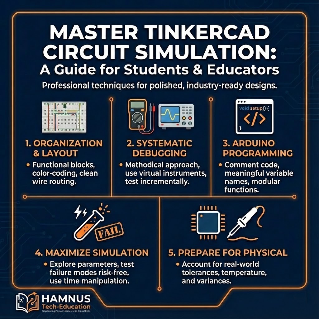
Best Practices for Using TinkerCAD in Electronics Projects
A Comprehensive Guide for Computer Engineering Students and Educators – Master circuit simulation with professional techniques.
TinkerCAD is a free, browser-based electronics simulation platform by Autodesk. It provides an invaluable environment to learn circuit design, Arduino programming, and electronics fundamentals without physical component costs or risks.
Circuit Organization and Layout Principles
Effective circuit design begins with thoughtful organization mirroring professional standards. Decompose circuits into functional blocks:
- Power supply sections – Voltage regulation and distribution ensuring stable power
- Input conditioning – Sensor interfaces requiring amplification, filtering, or level shifting
- Processing elements – Microcontrollers and logic circuits for decision-making
- Output drivers – LEDs, motors, displays interfacing with the physical world
Pro Tip: Use upper rail for positive voltage, lower for ground. Color-code wires: red=positive, black=ground, blue=digital, yellow=analog.
Wire Routing Best Practices
- Horizontal and vertical paths only – Orthogonal routing aids debugging
- Clean right-angle turns – Professional appearance and traceability
- Minimize crossings – Plan placement first; use colored jumpers when needed
- Proportional lengths – Avoid visual clutter from excessive wire loops
Component Placement
- Central IC placement – Minimizes wire lengths
- Consistent orientation – All resistors horizontal, all LEDs same direction
- Adequate spacing – Room for future modifications
- Signal flow direction – Left-to-right matching reading direction
Systematic Debugging
Methodical debugging separates competent engineers from frustrated tinkerers.
Debugging Hierarchy
- Power supply – Verify voltages with multimeter
- Current flow – Confirm circuit draws expected current
- Microcontroller – Test with simple LED blink
- Subsystems – Test peripherals individually
- Integration – Only after basics confirmed
Virtual Instruments
- Multimeters – At regulator outputs and junction points
- Oscilloscopes – For PWM and serial signals
- Pause function – Examine transient events impossible in real-time
Incremental Construction
Example temperature monitor build:
- Test sensor alone – verify voltage output
- Test Arduino with potentiometer – verify code
- Test LCD with fixed values
- Integrate only after each stage works
Arduino Programming Best Practices
Code Organization
- Header comments – Purpose, hardware, libraries, author, date
- Meaningful names –
temperatureSensorPinnotts - Centralized config – All pins as constants at top
Function Design
- Descriptive names:
readTemperature(),updateDisplay() - Single responsibility per function
- Local variables preferred over globals
Serial Debugging
- Print with labels:
Serial.print("Temp: "); Serial.println(temp); - Implement DEBUG constant for easy enable/disable
Simulation Features
Parameter Exploration
- Filter circuits – Sweep frequencies to develop intuition
- LED resistors – Try values to learn brightness relationships
- Timing constants – Vary RC values
Risk-Free Experimentation
- Create fault conditions safely
- Push beyond normal limits
- Test unconventional approaches
Strategy: Fail fast in simulation so physical builds proceed smoothly.
Time Manipulation
- Pause – Examine transients
- Slow motion – Detail PWM waveforms
- Fast forward – Speed through slow charging
Documentation
Project Documentation
- Descriptive titles and detailed descriptions
- Component annotations with text labels
- Multiple view exports
Version Management
- Milestone copies before changes
- Descriptive names:
Project_v1_Sensor,Project_v2_LCD
Physical Implementation
Simulation Limitations
- Tolerances – Real 1K resistors are 950-1050 ohms
- Temperature drift – Values change with heat
- Parasitic effects – Wire inductance affects high frequencies
- EMI – Physical circuits pick up noise
Component Selection
- Use E12/E24 standard values
- Test tolerance extremes
- Verify availability before finalizing
Collaborative Learning
- Peer review – Fresh eyes spot issues
- Community gallery – Discover new techniques
- Contribute work – Share with documentation
Get Started: tinkercad.com – Free for students!